Emergency Field VHF/UHF Transmitting Antenna
As an ARES member, I often ask myself this question: “What would I do if I was deployed to an
area but forgot to bring my antenna with me?”
After some research I found a very simple solution. It only requires a piece
of coax cable and a few simple items to construct an effective transmitting
antenna.
 (fig. 1)
 (fig. 1)
Theory
As amateur radio operators, we know that one of the simplest antennas to construct
is the dipole. Invented by Heinrich Hertz around
1886, the dipole antenna has been around since the dawn of radio. The half wave
center-fed dipole antenna has a feed point impedance around 73 ohms. Z in = 73 ohms + j42.5 ohms. We
are seeing some reactance here. To reduce this reactance, the ideal length of
the center-fed half wave dipole should be around 0.48λ
which makes Zin= 70 ohm. Most modern transceivers have an output impedance of
50 ohms, so with the load being 70 ohms our rig will be happy with the SWR at
around 1.25:1.
Using this theory mentioned above, we can easily
calculate the length of the dipole we want to construct. The formula to find any half wavelength in
linear feet is to divide 468 by the center frequency in MHz for the desired
working frequency range. Most VHF FM repeaters are using 145 MHz to 146.9MHz,
so let’s set 145 MHz as our center frequency. Therefor, 468/145 = 3.23 feet or approx.
39 inches for our half wavelength in this case. The reason I set 145 MHz as
center frequency is that in some situation you might need to use the weak signal
portion (SSB/CW operation) of the 2 meter band which is around 144.200 MHz.
Now that we know the linear
length of our half wave dipole, we can start making the antenna.You will need a
piece of 50 ohm coaxial cable (RG-58, RG-8U, RG-8X, LMR-240, LMR-400, etc.). A
piece of CATV 75 ohm cable such as RG-6 used by most home cable service
companies will work in a pinch, too! Remember,if this is for an emergency
situation,we use whatever material we can get our hands on!You will also need a
short piece of ½”-1 ½ ” diameter of non-conductive material(PVC, wooden dowel, etc.) at least 12 inches long
to hold your dipole on a mast.
Making the Antenna
Cut off the connector
at one end of the coaxial cable if there is one. Measure 19 inches from the tip of the cable. Circle-cut
the outer PE jacket of the coax cable, being careful here not to cut through or
nick the shielding of the coaxial cable.
Once cut, you can slide off the jacket and discard. Carefully separate the shield from the
insulated center wire down to where you did the circular cut. You can accomplish this several way. One way is to un-braid the outer shield down
to the cut PE. Another way is to un-braid
a small section near the base of the circular cut,
then pull the center insulated conductor through the opening. Once it is completely separated the center from
the shield. It should look like this.
Now your half wave dipole antenna is almost ready!
Next step is to fabric
some sort of mounting system to support using the piece of non-conductive
material as boom. This will allow you to
elevate and rotate your antenna. You can
use tape or other non-conductive fasteners secure your dipole elements to the
boom. Coil the coaxial cable just below
the feed point 4-5 turns, about 6 “ in diameter. By doing this you’ll create an RF choke to cut
off the common mode currents that might develop on the cable during
transmissions (see fig. 2).
 (fig. 2)
Common mode current in feedline(source: Wikipedia)
Possible Gain!
A ½ wave dipole has an
Omni directional radiating pattern off the broad sides. It has a theoretical gain of 2.15 db over ¼
wave antenna. We can achieve get some extra
gain and directivity out of this antenna by using a conductive mast as a
reflective element, just like a 2 element Yagi-Uda antenna! I ran some
simulation in MMANA antenna modeling software and see about 1.98 db. Front to
back ratio is around 5.26 db, beam width is about 100 degrees.
In order to take
advantage of the mast reflector, the placement of your dipole should be 8
inches in front of the conductive mast with the top-tip of your dipole being 4
inches lower than the top of the mast.
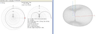 (fig. 3)
 (fig. 3)
2m dipole free space pattern using metal mast
as reflector
Dual band operation
How do you make this antenna work on 440 mhz? another popular amateur
frequency, most importantly our (Nassau County ARES) main repeater is on this
frequency. 440 MHz falls in the third harmonic of 146.7 MHz. So in theory the
145 MHz dipole is a 1.5 λ radiator on 440MHz.
 (fig. 4)
Free space pattern for a 2meter dipole operating on 440MHz.
To fix this, you will only need another piece of conductive
material. You can use a coat hanger or
any conductive wire. Straighten the wire and cut a piece measured 12.5 inches
long. Mark the center of this wire and put it 1 inch in front of with the 145
MHz dipole. Tape it down or use whatever
method to secure the wire. This wire should be parallel to the 145mhz dipole.
The added 12.5 inches element is called “open sleeve” radiator. Now the
radiating pattern looks like this.
 (fig. 5)
Summary
There are three
advantages of this antenna.
- No
soldering required.
- Dual
band operation.
- Achieve
extra gain or directivity by simply changing the mast material.
- Simple,
inexpensive construction using readily available parts.
In an actual emergency
situation this antenna can be quickly prepared and erected. Bandwidth is also adequate
for transmitting on the 2m and 70cm amateur bands.


Comments
Post a Comment